Network Cabling Design and Installing for Commercial Building and Data Center
วัตถุประสงค์ของหลักสูตร
เพื่อให้ผู้เข้ารับการอบรม มีความรู้และความเข้าใจเกี่ยวกับรายละเอียดการเดินสายสัญญาณตามมาตรฐาน TIA-568 และ TIA-569 ครบถ้วนทุกมาตรฐาน สำหรับอาคารพาณิชย์ และอาคารสำนักงานทั่วไป ตลอดจนมาตรฐาน TIA-942B สำหรับ Data Center เนื้อหาจะเน้นไปที่การออกแบบ การเดินสายสัญญาณ ทั้งในและนอกอาคาร รวมทั้งการคำนวณ และเลือกสายสัญญาณที่ได้มาตรฐาน TIA การออกแบบเดินสายสัญญาณและระบบเครือข่ายใน Data Center ตลอดจนมาตรฐานการวัดสายสัญญาณ เพื่อทดสอบประสิทธิภาพของสายสัญญาณหลังจากติดตั้ง ตามมาตรฐานสากล
หลังจากจบหลักสูตรแล้ว ผู้เข้ารับการอบรมจะสามารถ
เข้าใจหลักการออกแบบ Structured Cabling สำหรับการเดินสายสัญญาณ UTP และ Fiber Optic ที่ได้มาตรฐาน TIA-568 และ TIA-569 สำหรับอาคาร
เข้าใจมาตรฐานต่างๆ ของการเดินสายสัญญาณระบบเครือข่าย model และวิธีการนำสิ่งเหล่านี้ไปปรับใช้กับการออกแบบเครือข่าย
ออกแบบระบบเดินสายสัญญาณสำหรับผู้ใช้งานและระบบ Patching สำหรับอาคารพาณิชย์ ตามมาตรฐาน TIA-568 ครบถ้วน
เรียนมาตรฐาน Grounding และ Bonding ใน Data Center และอาคารสำนักงานทั่วไป
สามารถออกแบบวางระบบ เดินสายสัญญาณ และคำนวนการติดตั้งเครือข่ายได้จริง
ออกแบบระบบเดินสายสัญญาณเครือข่ายและระบบ Patching สำหรับ Data Center
ออกแบบระบบ Backbone สำหรับการเดินสายสัญญาณทั้งในที่ร่มและกลางแจ้ง
เลือก cabling containment/pathways ที่เหมาะสมสำหรับการติดตั้งระบบเครือข่าย
ใช้แนวทางการติดตั้งที่ถูกต้องและหลีกเลี่ยงข้อผิดพลาดทั่วไป
กำหนดเกณฑ์และวิธีการทดสอบที่เหมาะสมสำหรับระบบสายทองแดงและไฟเบอร์
มีความรู้และมีมาตรฐานการวัดสายสัญญาณทั้งที่เป็นแบบสายตีเกลียวและ Fiber Optic
จำนวนเวลาอบรม 2 วัน
ผู้ที่เหมาะเข้ารับการอบรม
ผู้รับเหมาออกแบบ วางระบบ เดินสายสัญญาณและติดตั้งเครือข่ายในอาคารพาณิชย์และอาคารทั่วไป
ผู้รับเหมาออกแบบ วางระบบ เดินสายสัญญาณและติดตั้งเครือข่ายใน Data Center
เจ้าหน้าที่ฝ่ายเทคนิค เดินสายสัญญาณ และติดตั้งอุปกรณ์เครือข่าย และกล้องวงจรปิด
วิศวกรออกแบบ ติดตั้งเดินสายสัญญาณในอาคาร และ Data Center
ผู้ดูแล หรือบริหารระบบไอที และเครือข่าย ประจำหน่วยงานต่างๆ
รายละเอียดหลักสูตร
Introduction to Structured Cabling System
Structured Cabling and Standardization
ANSI/TIA-568-C Cabling Standard
Subsystems of a Structured Cabling System
Differences Between ANSI/TIA-568-C and ISO/IEC 11801 Ed. 2.2
TIA-568.0-D Generic Telecommunications Cabling for Customer Premises
Telecommunications Cabling System Structure
Topology
Equipment Outlets (EOs)
Distributors
Cabling Subsystem 1
Cabling Subsystem 2 and Cabling Subsystem 3
Recognized Cabling
Cabling Lengths
Cabling Installation Requirements
Balanced Twisted-Pair Cabling
Maximum Pulling Tension
Minimum Bend Radius
Cable
Cord Cable
Cable Termination
8-Position Modular Jack Pin-Pair Assignments
Cords and Jumpers
Bonding and Grounding Requirements for Screened Cabling
Optical Fiber Cabling
Minimum Bend Radius and Maximum Pulling Tension
Polarity.
TIA-568.1D – Commercial Building Telecommunications Infrastructure Standard
Commercial Building Telecommunications Cabling Standard
Entrance Facilities
Equipment Rooms (ERs)
Telecommunications Rooms (TRs) and Telecommunications Enclosures (TEs)
Centralized Optical Fiber Cabling
Backbone Cabling (Cabling Subsystems 2 and 3)
Length and Maximum Distances
Recognized Cabling
Horizontal Cabling (Cabling Subsystem 1)
Recognized Cabling
Work Area
Open Office Cabling (MUTOA)
Maximum Work Area Cord Lengths
Consolidation Point (CP)
Difference between Commercial Wiring and data center cabling
Cabling System Planning and Design for Smart Buildings
TIA-568.2-D Balanced Twisted-Pair Telecommunications Cabling and Components Standard
Channel and Permanent Link Test Configurations
Definitions of Electrical Parameters
Recognized Categories of Balanced Twisted-Pair Cabling and Components
Channel Transmission Performance
Channel Propagation Delay Skew
Augmented Category 6 Channel Requirements
Permanent Link Transmission Performance
Permanent Link Propagation Delay Skew
Horizontal Cable Transmission Performance
Horizontal Cable Propagation Delay Skew
Bundled and Hybrid Cable
Patch Cord Transmission Performance
Patch Cord Cable Construction
Cable Quality and Network Performance
TIA-568.3-D Optical Fiber Cabling Components
Optical Fiber Cabling Components
Optical Fiber Connector
Color Identification
Optical Fiber Telecommunications Outlet Required Features
Optical Fiber Connector (Mated Pair)
Patch Cords
Horizontal Cabling and Administration - Commercial Building
Standard diagram recap: ANSI/TIA-568
Administration: Interconnect and cross-connect
Angled and flat panels
Creating a cabling schematic design
Convert schematic into physical layout
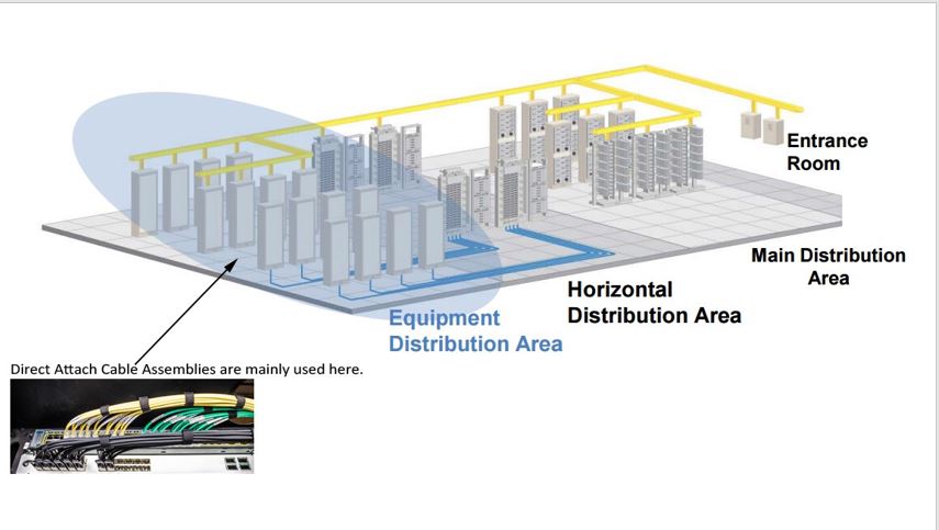
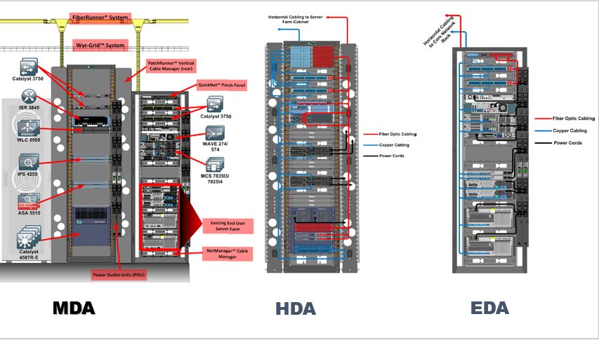
Horizontal cabling and Administration - Data Centre
Standard diagram recap: TIA-942
Data Centre cabling best practice
Traditional 3 layers network design/ Spine and Leaf network design
Select termination hardware
Administration design
ToR/EoR/Spine & Leaf cabling design
Network Cabling
Network Cable
Optical Fiber
DAC
Designing Structured cabling for ToR
patch panel/rack layout for ToR/EoR
Building Backbone - Commercial Building
Backbone diagram
Equipment Room (ER) /Telecommunications Room (TR) design guide line
Calculate the Fiber backbone requirements for Telecom Room
Recognized cables
Backbone Patch panels
The maximum backbone distances
Converting the schematic design into patch panel/ rack layout
Fiber backbone cabling in buildings
Backbone cabling speeds
Optical fiber in the backbone
10 Gbps optical fiber backbone
Migrating to 40 Gbps and 100 Gbps
Backbone distances
Existing installations and support for 40 Gbps and 100 Gbps
New installations and support for 40 Gbps and 100 Gbps
Building Backbone - Data Centre
TIA-942 based backbone topology
TIA-942 backbone requirements
Recognized backbone cable
ToR/EoR/Spine and Leaf
Backbone distance estimation
Resiliency of backbone cable routes
Creating cabling schematic design
Converting the schematic design into patch panel/ rack layout
Field and Fusion Termination for fiber connectors
Pre-terminated fiber trunk and copper cables
ANSI/TIA569-E Cable pathway and spaces design
ANSI/TIA569-D Cable pathway and spaces
Telecommunications Pathways and Spaces
Design Considerations
Building Spaces
Temperature and Humidity Requirements
Common Requirements for Rooms
General and Architectural
Racks and Cabinets
Distributor Room (Equipment Room/Telecommunications Room)
Architectural and Environmental
Entrance Room or Space
Distributor Enclosure (Formerly Telecom Enclosure)
Equipment Outlet (EO)
Multiuser Telecommunications Outlet Assembly
Consolidation Point
Access Provider Spaces and Service Provider Spaces
Multi-Tenant Building Spaces
Building Pathways
Types of Pathways
Areas Above Ceilings
Access Floor Systems
Cable Support Systems
Underfloor Duct Systems
Cellular Floor
Perimeter Raceways
Pathway Separation from EMI Sources
Separation Between Telecommunications and Power Cables
Separation from Lighting
Grounding and Bonding
Cable Tray and Cable Runway
Conduit
Other In-Floor Pathways
Surface Raceway
Vertical Pathway – Sleeves or Conduits, Slots
Firestopping
Campus / Outdoor Backbone Design
Common campus cable installation and cable types : Aerial cable / Direct-buried / Underground in-conduit
Outdoor cable installation planning
Approved ground for surge protector
Creating a schematic diagram
Converting a schematic into a physical layout
Site Inspection and Testing
Installation common issues
Copper testing standard
Permanent link / Channel / Patch cord / MPTL testing configuration
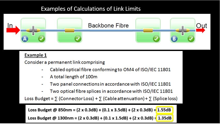
Fiber testing standard
Tier 1 & 2 certification
Fiber link definition
Fiber testing steps
Fiber inspection and cleaning
Calibrating the test sets - 3 methods
หากท่านสนใจสามารถสอบถามเพิ่มเติมได้ที่ T. 081-6676981, 089-7767190,
02-2740864, 02-2740867
![]() Facebook.com/cyberthai
Facebook.com/cyberthai ![]() Line ID : cyberthai
Line ID : cyberthai
![]() หรือ :This email address is being protected from spambots. You need JavaScript enabled to view it. , This email address is being protected from spambots. You need JavaScript enabled to view it.
หรือ :This email address is being protected from spambots. You need JavaScript enabled to view it. , This email address is being protected from spambots. You need JavaScript enabled to view it.


